The story so far
In the first part of this series I described the problem I was having, my hypothesis as to the source of the issue, and the steps I would take to test my hypothesis. This post describes the first step needed to begin testing...developing the IoT sensor rig.
Blog Series Table of Contents
Part 1 - Problem Space
Part 2 - Electronics <-- This post
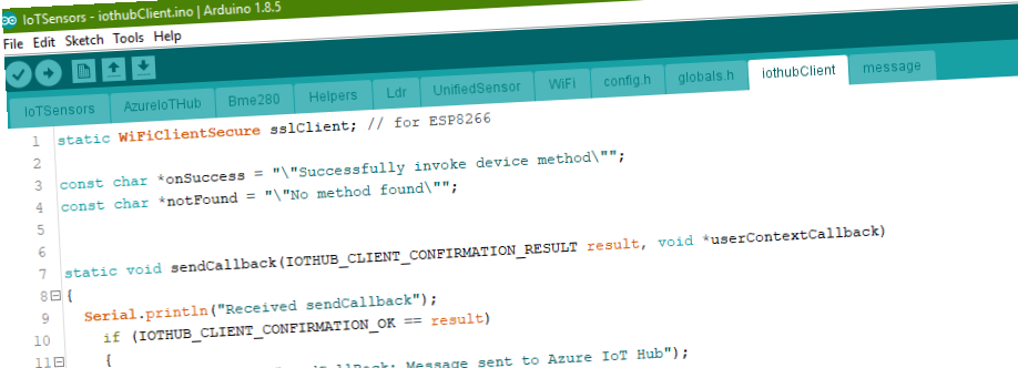
Part 3 - ESP8266 Code
Part 4 - Azure IoT Hub
Part 5 - Azure Stream Analytics
Part 6 - Power BI
Part 7 - Drawing Conclusions
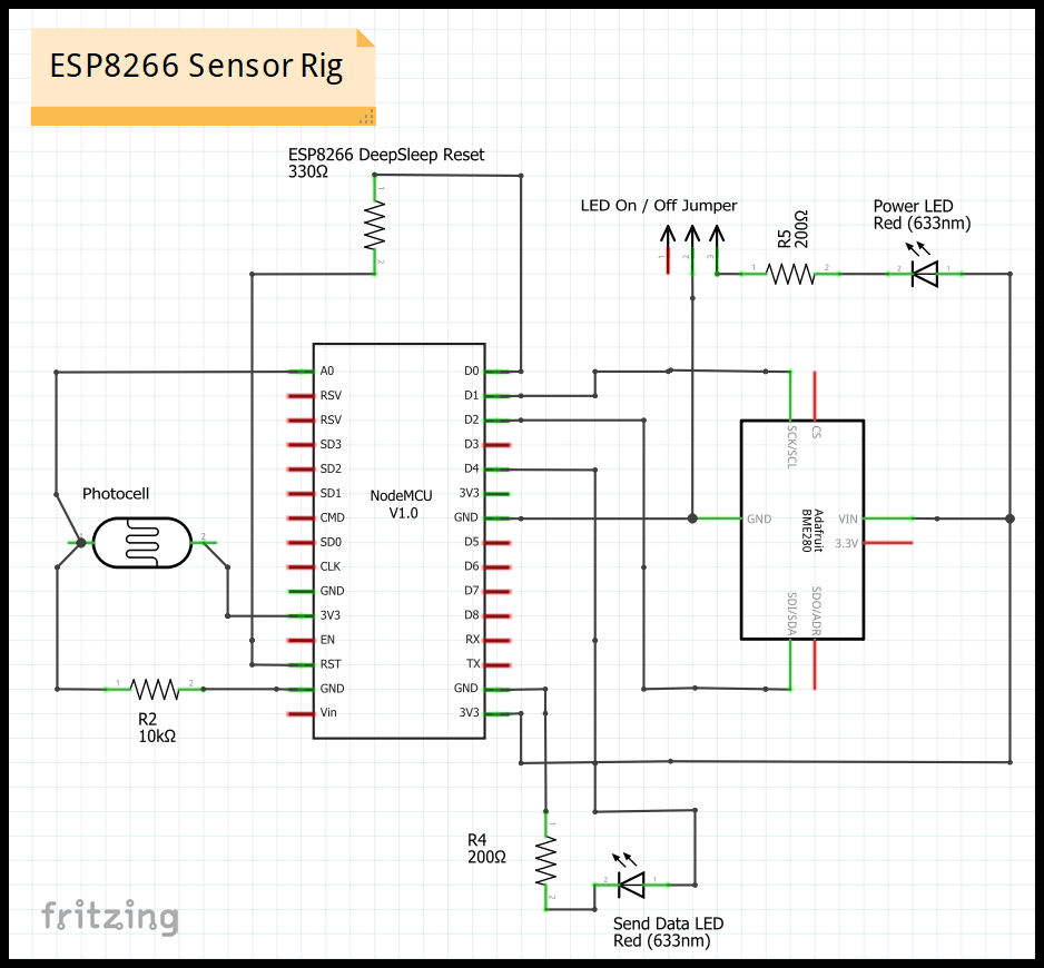
The Sensor Rig
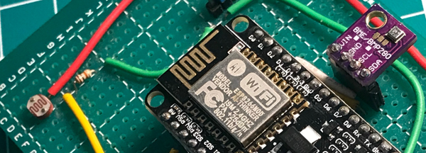
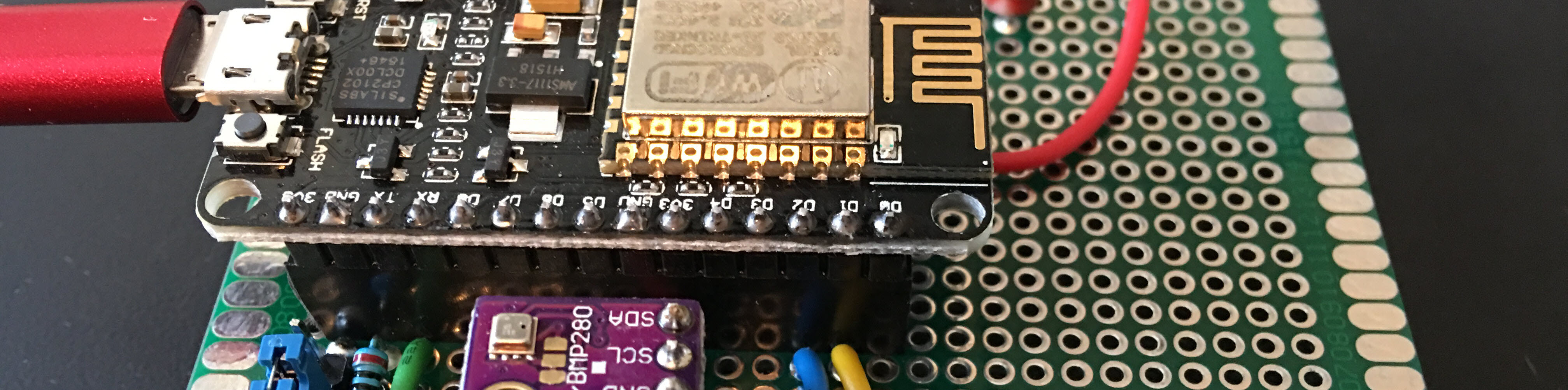
The first step is to design and code the sensor rig. This rig has 4 important parts/circuits and a couple of non-essential LEDs.
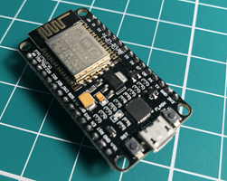
- ESP8266 (ESP-12e) Dev Board
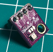
- BME280 I2C integrated environment unit
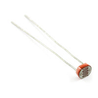
- Standard photocell
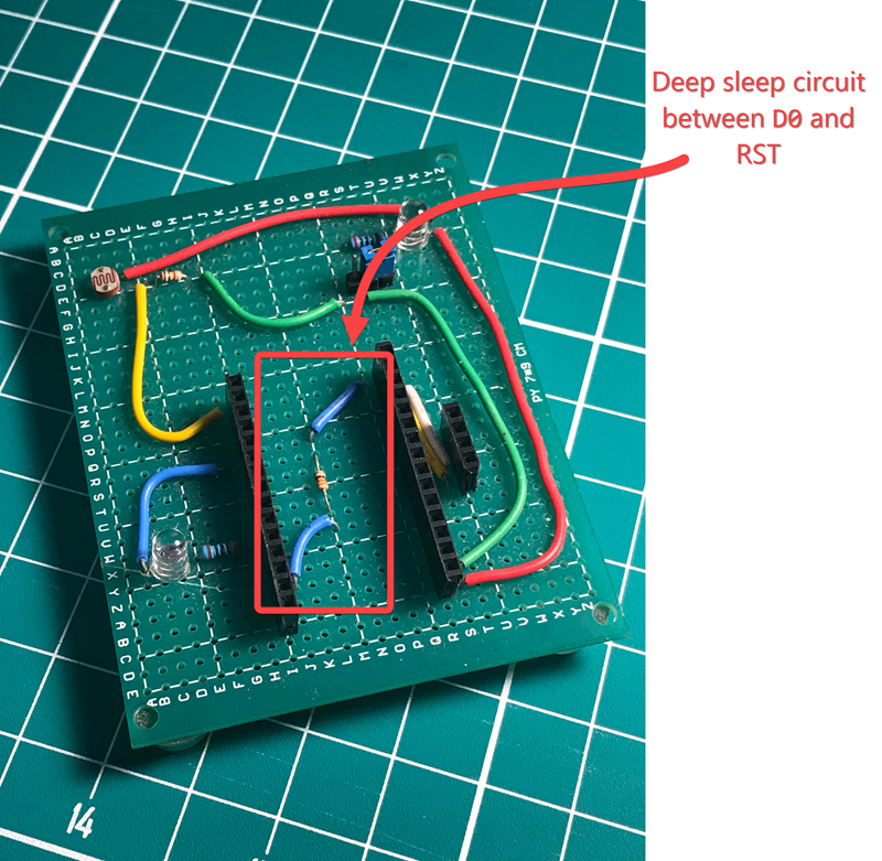
- Circuit between
D0andRST(with 330 ohm resistor) to support Deep Sleep mode
You can skip both LEDs if you like. The code will cause the ESP8266 onboard LED (attached to D4/GPIO2 to flash when uploading to IoT hub. I just wanted to know that power was flowing on the 3.3v rail (power LED) and a more obvious indicator that the data was accepted by Azure IoT Hub (Send Data LED).
Schematic
Board implementation
To make this project a bit easier I decided to use female pin headers to create a socket for the ESP8266 and BME280 boards. This let's me swap out either part if I happen to do something stupid, like over-current or over-voltage the rig.
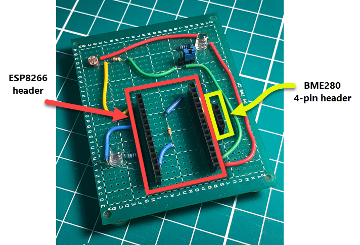
To make soldering easy, I attached the female header to the ESP, placed the header into the prototype board, taped the ESP in place, and then soldered the two end pins on each header. With that done, I could remove the ESP and finish soldering the remaining header pins.
I used red wires to carry 3.3v and green to carry GND. All other colors are signal wires.
Considerations for Deep Sleep
The ESP8266 has a DeepSleep mode that turns off everything except the real-time clock. The RTC will wake the ESP after a set interval. This is a necessity if you are planning to use battery power to run this rig. To perform this action we need to connect the Reset (RST) and Wake (D0) pins on the ESP board and write a little code to trigger it.
The D0 pin is special in that it provides the Wake message to the RST pin, as you can see in the pinout chart below.
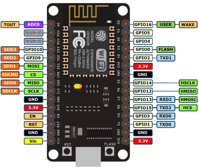
ESP8266 NodeMCU development board pinout
Conclusion (for now)
That about does it for the electronics in this project. It's not really a difficult build. Getting the I2C and analog pin wiring right is about the hardest part.
In the next post we will get the ESP8266 talking to wifi and then to Azure IoT Hub.
Blog Series Table of Contents
Part 1 - Problem Space
Part 2 - Electronics <-- This post
Part 3 - ESP8266 Code
Part 4 - Azure IoT Hub
Part 5 - Azure Stream Analytics
Part 6 - Power BI
Part 7 - Drawing Conclusions


Comments