The story so far...
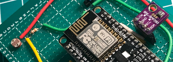
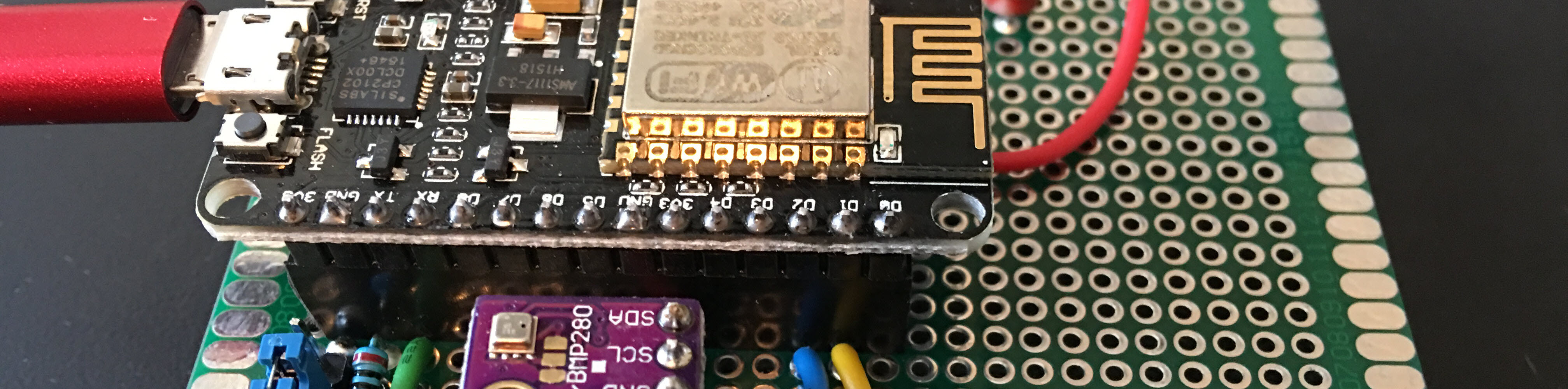
In the first part of this series I described the problem I was having, my hypothesis as to the source of the issue, and the steps I would take to test my hypothesis. In the second post I described the electronics that I built to start capturing environmental sensor data. This post describes the next step needed to begin testing...writing the code for the IoT sensor rig to send telemetry data to Azure IoT Hub.
Blog Series Table of Contents
Part 1 - Problem Space
Part 2 - Electronics
Part 3 - ESP8266 Code <-- This post
Part 4 - Azure IoT Hub
Part 5 - Azure Stream Analytics
Part 6 - Power BI
Part 7 - Drawing Conclusions
The Code
All of the code for the ESP8266 can be downloaded from my GitHub repo. Some of the code is original work, but most of it is adapted from the following sources.
- Azure IoT Hub connection through MQTT - Connect Adafruit Feather HUZZAH ESP8266 to Azure IoT Hub in the cloud
- ESP8266 WiFi connection without hard-coding SSID and Key - WiFiManager by tzapu
- Retrieve GUID from uuidgenerator.net over HTTPS - HTTPSRequest.ino example from ESP8266 library
- Set the real-time clock on ESP8266 - NTPClient library
- Calculate time with TZ consideration - Arduino TimeZone Library by Jack Christensen
- ESP8266 DeepSleep to reduce battery consumption - Making the ESP8266 Low-Powered with Deep Sleep
The basic flow of logic is pretty simple. Every time the microcontroller starts/wakes from sleep it performs the following steps.
- Connect to local wifi
- Get current date/time from NTP
- Get a GUID (message id)
- Get the sensor data
- Connect to Azure IoT Hub
- Publish the data to IoT Hub
- Wait for a reply from IoT Hub
- Deep Sleep for 15 mins
Arduino Prerequisites
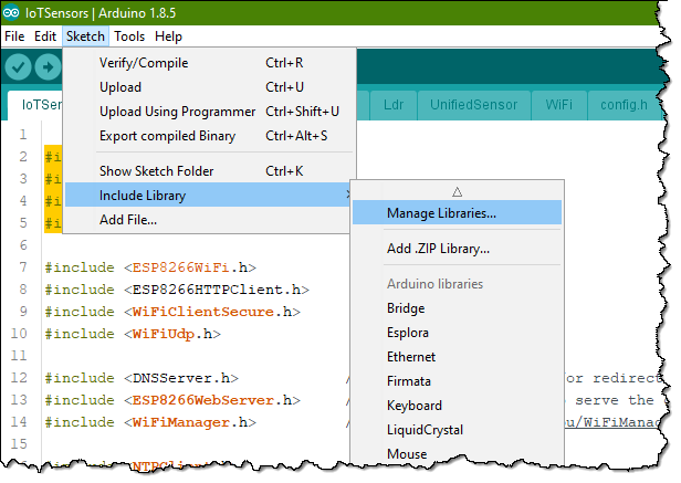
You need to start by making sure the Azure IoT SDK for C is installed into your environment. If using the Arduino IDE (mine is v1.8.5), go to Sketch -> Include library -> Manage Libraries....
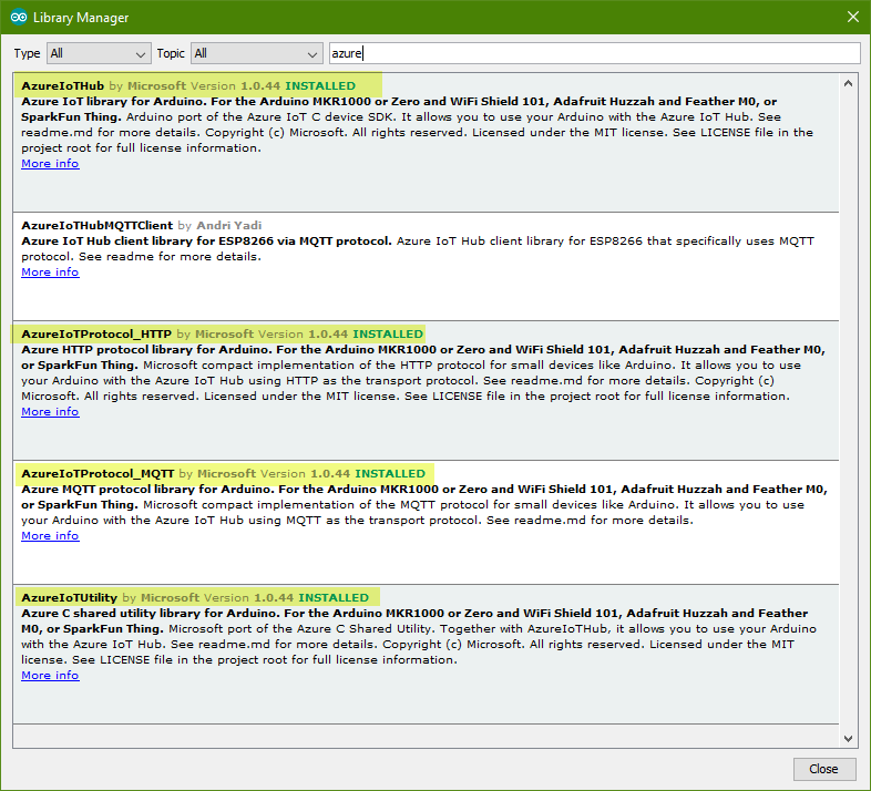
In the Library Manager search for azure. This will bring up the available libraries from Microsoft (and others). For this project I used AzureIotHub, AzureIoTUitlity, and AzureIoTProtocol_MQTT.
Setup Azure IoT Hub
If you haven't done so already, Create an Azure IoT Hub instance and then Register a device in the IoT hub for your device. Once that is setup you need to grab some info so your device can connect to Azure IoT Hub.
Generate a SAS token for your device
My code relies on direct use of MQTT so I need to grab a SAS token for each device. I use Device Explorer v1.7.0 to help with debugging device to Iot Hub messages. It also has the ability to generate SAS tokens for you.
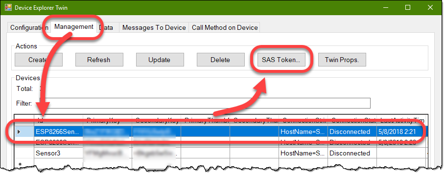
In Device Explorer, after making your connection to your IoT Hub:
-
Go to the Management tab.
-
Select your device and then click on the SAS Token... button.
-
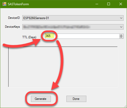
In the SAS Token dialog, enter the duration of the SAS token (in days) in hte TTL (days) field then click the Generate button.
-
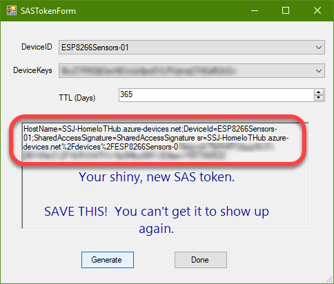
The bottom half of the SAS Token dialog will be populated with your shiny, new SAS token.
Speaking of code, open up the globals.h file and enter your device name (line 1) and SAS token (line 6).
#define DEVICE_ID "Your sensor name goes here"

#define LED_PIN 2

//SAS token for Azure IoT hub device
static char* connectionString = "IoT Hub Device SAS Token Goes Here"

#define MESSAGE_MAX_LEN 256

// Interval time(ms) for sending message to IoT Hub
#define RETRY_INTERVAL 200   //in ms
#define DEEP_SLEEP_SECS 900  //15 mins
Ok, that has you hooked up to Azure IoT Hub. If you have just an ESP8266 and don't want to mess with the BME280 then open up UnifiedSensors.ino and comment out line 4 and uncomment line 5 so your code looks like the block below. This will use fake sensor readings and avoid hitting the BME280 code.
struct SensorData retrieveSensorData(void)
{
  SensorData dat;
  //dat = getBme280Readings();
  dat = getFakeWeatherReadings();
  dat.light = getLdrReadings();
  dumpSensorDataToSerial(dat);
  return dat;
}
Upload code and first run
Let's compile and upload the code to the ESP8266 using the Arduino IDE. Once it's uploaded, launch the Arduino Serial Monitor and set the baud rate to 115200. You should start getting some data on the monitor from the ESP8266 that looks something like this:
*WM:
*WM: AutoConnect
*WM: Connecting as wifi client...
*WM: Using last saved values, should be faster
*WM: Connection result:
*WM: 0
*WM: SET AP STA
*WM:
*WM: Configuring access point...
*WM: IoTSensors
*WM: IoTSensors
*WM: AP IP address:
*WM: 192.168.4.1
*WM: HTTP server started
*WM: Request redirected to captive portal
*WM: Handle root
*WM: Scan done
*WM: Marbles-guest
*WM: -34
*WM: --Redacted Network--
*WM: -35
*WM: --Redacted network--
*WM: -85
*WM: Sent config page
*WM: Request redirected to captive portal
*WM: Handle root
*WM: WiFi save
*WM: Sent wifi save page
*WM: Connecting to new AP
*WM: Connecting as wifi client...
*WM: Connection result:
*WM: 3

 == WiFi Dump =================================================
   IP ADDR: 192.168.3.126
   MAC ADDR: 84:F3:EB:B3:3E:61
   SSID: Marbles-guest
   Channel: 1
   Is Connected: 1
 ==============================================================
Lines 1-6 are trying to connect to the last-known wifi access point. Since this is the first run on a new ESP8266, there hasn't been a connection, so that fails. Lines 7-14 show that e WiFiManager code is setting up the ESP as an access point with a network SSID of IoTSensors (line 10) and a password of IoTSensors (line 11). At this point the ESP8266 is waiting for you to connect to it. I used my phone to connect to the IoTSensors network. As soon as I did, WiFiManager generated a captive portal page (lines 15-16) to let me continue.
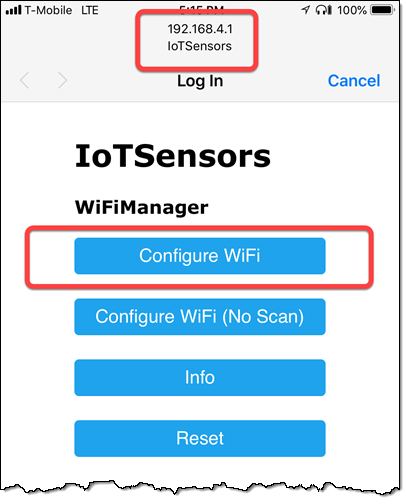
At the top of the picture you can se that I've connected to the IoTSensors wifi network and my IP address is 192.168.4.1. I can now click on the Configure WiFi button to have WiFiManager scan for nearby networks and present the connection screen (lines 17-24).
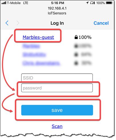
On the connection page I can either type in an SSID or select one of the nearby ones. I'll then need to enter the passphrase for the network and click the Save button. This will cause the ESP8266 to store the network credentials in EEPROM (lines 25-28), drop it's access point mode (line 29), and connect to the selected network (lines 30-40). From this point forward, the ESP8266 will use the cached network credentials. No more hard-coding your network info into your Arduino code.
Connecting to AzureIoT Hub
Once connected to the wifi network the ESP will start sending data to your IoT Hub. This is perfomed by two functions, configureAzureIoTHubConnection() and sendSensorDataToAzureIoTHub().
Both of these functions rely on the Azure IoT SDK for C so we need to add a couple of #includes to our IoTSensors.ino file.
#include <AzureIoTHub.h>
#include <AzureIoTUtility.h>
#include <AzureIoTProtocol_MQTT.h>
#include <ArduinoJson.h>
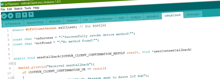
The rest of the work happens in the AzureIoTHub.ino file.
configureAzureIoTHubConnection()
The configuration of the SDK is pretty straight-forward. You need to create a handle to the IoT Hub based on your SAS token (connectionString) and communication protocol (MQTT_protocol) (lines 3-5). Once that is successful, we set a few callbacks.
ITHUB_CLIENT_LL_HANDLE configureAzureIoTHubConnection(void)
{
    iotHubClientHandle =
         IoTHubClient_LL_CreateFromConnectionString(connectionString,
                                                    MQTT_Protocol);
    if (iotHubClientHandle == NULL)
    {
        Serial.println("Failed on IoTHubClient_CreateFromConnectionString.");
        while (1);
    }

    IoTHubClient_LL_SetOption(iotHubClientHandle,
                             "product_info",
                             "IoTSensors");
    IoTHubClient_LL_SetMessageCallback(iotHubClientHandle,
                                       receiveMessageCallback,
                                       NULL);
    IoTHubClient_LL_SetDeviceMethodCallback(iotHubClientHandle,
                                            deviceMethodCallback,
                                            NULL);
    IoTHubClient_LL_SetDeviceTwinCallback(iotHubClientHandle,
                                          twinCallback,
                                          NULL);
}
IoTHubClient_LL_SetMessageCallback()
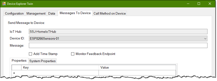
The first callback is in IoTHubClient_LL_SetMessageCallback(). This callback happens when the ESP8266 receives a cloud-to-device (C2D) message. You can test this callback by sending a message from Device Explorer's Message to Device tab.
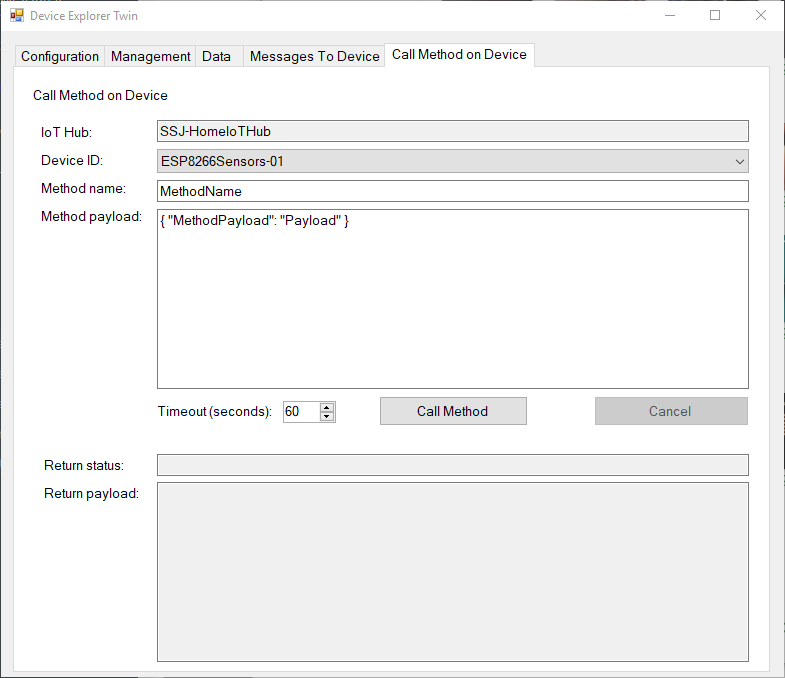
IoTHubClient_LL_SetDeviceMethodCallback()
The second callback is in IoTHubClient_LL_SetDeviceMethodCallback(). This callback is triggered when the device connects to Azure IoT Hub and there is a message waiting to tell the device to trigger a specific method.
For example, you have an IoT device that monitors the temperature of a piece of equipment and sends that data to IoT Hub. An Azure Function is constantly monitoring these temps and when the temp gets over a pre-defined threshold the Function sends a cloud-to-device message to a second IoT device that controls a fan. This message tells the fan to turn_on() which cools the first device. When the temp of the first device goes below the threshold for a given period then the Function can send a second message to turn_off() the fan.
You can test this callback by sending a message from Device Explorer's Call Method on Device tab.
IoTHubClient_LL_SetDeviceTwinCallback()
The last callback is in IoTHubClient_LL_SetDeviceTwinCallback(). This callback happens when a change occurs in the Device's Device Twin in IoT Hub as a result of a change in the Device Twin's configuration. When this happens the device should update itself with the new configuration settings.
You can test this callback by:
- Open Device Explorer and change to the Management tab.
- Select a device from the Devices grid.
- Click on the Twin Props. button.
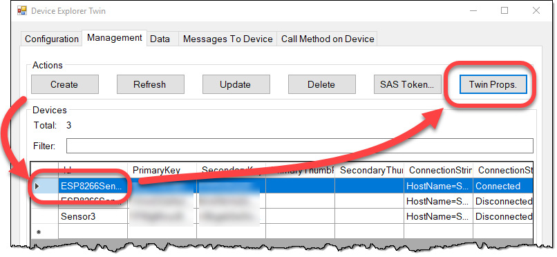
-
The Device Twin window opens showing all of the properties IoT Hub knows about my sensor device.
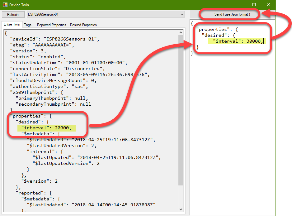
-
On the Device Twin windows note the body shows all of the properties IoT Hub knows about my sensor device. Lines 15-17 show the desired interval property setting.
  "properties": {
    "desired": {
      "interval": 20000,
- Let's say that the
intervalvalue is the Deep Sleep duration of the ESP8266. Then if I want to change the duration without going to that specific device and reflashing the code, I can set the new value in the right-hand pane to update the Device Twin. - Updating the Device Twin will trigger the
twinCallback()method that I provided to theIoTHubClient_LL_SetDeviceTwinCallback()method. - Inside
twinCallBack()I can get the new interval and save it to EEPROM so the device will begin using it on the next wake cycle.
Sending sensor data to Azure IoT Hub
The sending part is fairly straight-forward as well. We send the method a SensorData struct instance containing all of the retrieved and calculated sensor data. We also send the current date/time and an id for the message (GUID).
sendSensorDataToAzureIoTHub()
void sendSensorDataToAzureIoTHub(struct SensorData dat, String formattedTime, String messageId)
{
  if (!messagePending && messageSending)
  {
      char messagePayload[MESSAGE_MAX_LEN];
      generatePayload(data, formattedTime, messageId, messagePayload);
      sendMessage(iotHubClientHandle, messagePayload);
      ThreadAPI_Sleep(sendRetryInterval);
  }

  int i = 1;
  while(messagePending && messageSending){
    Serial.printf("    Waiting for the sendCallback to be triggered: %d \n", i);
    IoTHubClient_LL_DoWork(iotHubClientHandle);
    yield();
    ThreadAPI_Sleep(sendRetryInterval);
    i++;
  }
}
We first check to see if a prior message is still waiting in the queue (line 3), and if so, we wait for it to clear (lines 11-18). When we are clear to send we generate the data payload (line 6), send the message to the IoT Hub Client in the Azure IoT SDK for C (line 7), and wait a bit to give the IoT Hub Client a chance to fire off the message to Azure IoT Hub (line 8).
Lines 11-18 exist because of an issue that I had. I wasn't waiting long enough for the IoT Hub Client to finish sending the payload to Azure IoT Hub. When the ESP8266 went into Deep Sleep it cut off the transmission of the message so I was never seeing messages arrive in Azure IoT Hub. These lines let the IoT Hub Client perform its duties before letting the ESP8266 go into Deep Sleep.
generatePayload()
void generatePayload(struct SensorData sData, String formattedTime, String messageId, char *payload)
{
    memset (payload, 0, MESSAGE_MAX_LEN);

    StaticJsonBuffer<MESSAGE_MAX_LEN> jsonBuffer;
    JsonObject &root = jsonBuffer.createObject();
    root["deviceId"] = DEVICE_ID;
    root["messageDateTime"] = formattedTime;
    root["messageId"] = messageId;
    root["tempC"] = round(sData.temperatureC);
    root["tempF"] = round(sData.temperatureF);
    root["humidity"] = round(sData.humidity);
    root["dewPtC"] = round(sData.dewPointC);
    root["dewPtF"] = round(sData.dewPointF);
    root["pressure"] = sData.pressure;
    root["light"] = sData.light;

    root.printTo(payload, MESSAGE_MAX_LEN);
}
The message payload is simply a string that contains the sensor data formatted as JSON. Nothing crazy-special here.
sendMessage()
static void sendMessage(IOTHUB_CLIENT_LL_HANDLE iotHubClientHandle,
                        char *buffer)
{
    IOTHUB_MESSAGE_HANDLE messageHandle =
            IoTHubMessage_CreateFromByteArray(
                        (const unsigned char *)buffer,
                        strlen(buffer));

    if (messageHandle == NULL)
    {
        Serial.println("sendMessage: Unable to create a new IoTHubMessage.");
    }
    else
    {
        Serial.printf("sendMessage: Sending message: %s.\r\n", buffer);
            if (IoTHubClient_LL_SendEventAsync(iotHubClientHandle,
                                            messageHandle,
                                            sendCallback,
                                            NULL)
            != IOTHUB_CLIENT_OK)
        {
            Serial.println("sendMessage: Failed to hand over the message to IoTHubClient.");
        }
        else
        {
            messagePending = true;
            Serial.println("sendMessage: IoTHubClient accepted the message for delivery.");
        }

        IoTHubMessage_Destroy(messageHandle);
    }
}
The sendMessage() function fires the message off to the IoT Hub Client and registers the sendCallback() handler to let us know when the message is finally sent to Azure IoT Hub. Since we hand off the message to the Azure IoT Hub SDK, we have to wait for it to connect, transmit and close before we can go into Deep Sleep.
Conclusion (for now)
That's it for the ESP8266 electronics and code. The next post will discuss the data arriving in Azure IoT Hub and how we can work with it.
Blog Series Table of Contents
Part 1 - Problem Space
Part 2 - Electronics
Part 3 - ESP8266 Code <-- This post
Part 4 - Azure IoT Hub
Part 5 - Azure Stream Analytics
Part 6 - Power BI
Part 7 - Drawing Conclusions


Comments